2

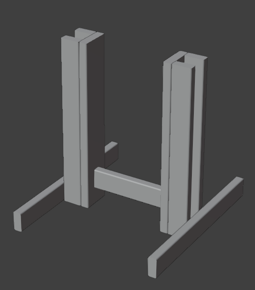
I'm designing a stool/chair/sitting-thing intended to be made from 2x4s and 2×6s. The main vertical portion (i.e. that's supposed to support the user's weight) is a sort of 'h' frame, of which the "pillars" are "C"-shaped made with a 2×6 and two 2×4's, with the open end outward.

While this will stand on its own, the side-to-side stability is limited, so I'd like to add a pair of horizontal boards to the bottom. Again, to maximize stability, I want them outside the "pillars". However, for ease of storage/transport, I don't want them to be permanently attached. (In particular, I prefer for the center section to be no wider than 5½", and I'd also prefer for the stabilizer boards to not have anything permanently attached.)

How can I attach the 'stabilizer boards'?

One idea is to use 'L' brackets and bolts, but a) finding the right size may be tricky (especially as most brackets expect to be used with smaller-diameter screws) and b) I wonder about how much shear strength the brackets will have. Another idea is to use bolts that go all the way through the pillars, but that would require 7" bolts. A foursome of heavy screws would easily do the job, except I'd lose the ability to disassemble and reassemble the piece.

(I'd also be open to alternative means of keeping this from tipping sideways, but keeping the disassembled volume low is also desirable.)


Since a picture will almost surely make this easier to understand:

visualization

Everything but the bottom outside boards is (permanently) screwed together. I need to attach the bottom outer (2×4) boards to the "pillars", keeping in mind they're intended to keep the thing upright when a person (for safety's sake, let's say this person weighs ~300lbs) is "trying" to tip it over.

p.s. I am a novice with limited equipment (this design is intended to be buildable with nothing more complicated than a drill and a miter saw), so solutions that don't require special tools or complicated techniques are preferred.
9
  • Welcome! Kudos for attaching the picture, but I am not sure I follow the overall structure of the chair. (Maybe it’s just me!) Will there be two of these H-sections or just one? Where does the seat go and where does the sitter face? (From what you called “sideways”, I am inferring that that sitter faces north-west in the image?) Will there be any back? Also, out of curiosity, what are the design goals that made you forgo one of the standard designs?
    – stanch
    Commented Aug 7 at 21:41
  • @stanch, I don't want to show the whole design; this is just the lower part (slightly edited), but it's the entire lower part. The complete design is... unusual, with what makes it unusual being the purpose of creating the design. "Northwest" works as the facing direction. ("Southeast" would also work since what's in the picture is symmetrical in both X and Y, though the complete design isn't.) The reason to not use a standard design is that the 'H' section is more-or-less "flat", and I'm trying to keep it that way.
    – Matthew
    Commented Aug 7 at 22:14
  • @stanch, this is not the real chair, but it's using some similar ideas. In particular, if you imagine the seat and back being detachable, you can probably imagine it shipping as a flat-pack. Of course, it isn't going to be sideways-stable. I'm dealing with something similar; all the vertical supports are in the middle, and I'm trying to keep them "thin" to minimize volume in the disassembled state. The obvious way to do that is to attach horizontal pieces to the main frame at the base, but that brings me to this Question.
    – Matthew
    Commented Aug 7 at 22:31
  • Thanks for the extra info! In this design, would you agree that the seat rocking sideways on the support is also a concern? Back to your original question, one idea that came to my mind is to lower the bar connecting the H pillars a bit and cut square notches in the stabilizers so that it slots into them. (They would go inside the H and not outside.) No fasteners needed. (Speaking of fasteners, properly jointing and gluing the permanent parts would add a lot of strength and longevity compared to just screwing them.)
    – stanch
    Commented Aug 8 at 0:04
  • 1
    Side tip: put adjustable feet (“furniture levelers”) on the 4 corners. Commented Aug 8 at 13:37

2 Answers 2

3

One idea is to use 'L' brackets and bolts

While you can get beefier L-brackets than the typical ones, which aren't made to take much strain, or better, certain kinds of lumber connectors such as Strong-Ties, you could avoid hardware entirely and just screw the components together directly.

Pre-drilled holes correctly sized for the respective purposes — for clearance on the stabiliser boards and as pilot holes in the uprights — will ensure maximum hold.

You can thread directly into wood, as of course any wood screw does when it's first inserted, but also with machine screws and they can create a remarkably strong hold. Machine-screw threads can be forced in or cut with a rudimentary tap1. This works best in hardwoods but might be sufficient in softwood (even construction lumber of so-so quality), especially if the holes are reinforced2. I have a few workshop tools and jigs made from common softwoods with screws that need loosening and retightening as needed and all have held up well over years of use.

However if you want to err on the side of caution just add metal threaded inserts or T-nuts, or bury a nut in the wood of the uprights, as was common historically with workbench construction. See more on all these in Embedded nut for using machine screws?

Another idea is to use bolts that go all the way through the pillars, but that would require 7" bolts.

If you did still want to go all the way through, 7" bolts are not hard to find and shouldn't be prohibitively expensive. But if preferred, for any reason, threaded rod AKA all-thread could be substituted; you just install nuts on both ends (and washers of course to spread the load under the nuts to minimise crushing).


1 See How can you make a regular screw into a self tapping screw? for more.

2 Screw holes can be reinforced using superglue/CA to strengthen the wall. For even greater strength use epoxy, but the curing time is much longer and you shouldn't stress the threads until after a full cure.

7
  • I guess "barrel" a.k.a. "cross dowel" nuts could be another option. I'm getting the idea I probably ought to use some dowels (not glued in, or at least glued only on one side) as reinforcement, though... those can take a lot of the load forces while the bolts just need to keep the stabilizers from falling off...
    – Matthew
    Commented Aug 8 at 20:50
  • Yes barrel nuts are another option, I didn't mention them directly as they can be harder to get and tend to cost more (lots more for me locally)... while providing not much extra strength and being far harder to install, because everything must align perfectly which can be a drilling challenge. Not sure about how you mean the dowels to be used.
    – Graphus
    Commented Aug 9 at 5:49
  • The main forces that need to be resisted are the stabilizer boards rotating relative to the pillars. Adding dowels between the two will allow the dowels to take most of that force. At that point, cheap brackets are probably fine too (especially if they have some play), since the bracket is just holding the stabilizer boards against the pillars. Right now I'm leaning toward burying T nuts, as I can probably get away with all connections using those (and no brackets anywhere).
    – Matthew
    Commented Aug 9 at 17:41
  • Er, the screws already resist that rotation. Screws are fixating devices & they could provide all the resistance to rotation that you could ask for (the right screws, used in sufficient number). I'm all in favour of reinforcing however, it is rarely a bad idea to make something stronger and even on normal furniture the tradition is to overbuild. However here the dowels might supplant a screw at each location, which would actually materially weaken things. If further stabilisation is desired, housings (dados) in the stabilisers are one classic solution. Can also be 'faked' with glue blocks.
    – Graphus
    Commented Aug 10 at 6:47
  • Recall first that the goal is to not use screws to attach the stabilizers. "Used in sufficient number" is the problem. I'm inclined to use fender washers with these (partly for aesthetic reasons, if I'm being honest), which means I can only get two bolts per stabilizer board (one on each side), at least if I don't want a washer extending beyond the top of the boards. Two bolts is fine for the negligible tension load, but I can add four (additional) dowels (one above and one below each bolt). Overkill? Maybe, but like you say, better to overbuild...
    – Matthew
    Commented Aug 10 at 17:57
0

To elaborate on what I wrote in the comments:

Idea 1

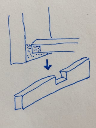
lower the bar connecting the H pillars a bit and cut square notches in the stabilizers so that it slots into them. (They would go inside the H and not outside.)

Here is a very rough sketch (not to scale):

stabilizer with a notch

Hopefully this addresses your doubts (“I don't see how slots would work”). The H-structure presses the stabilizers to the floor, and the notch houses the stretcher to resist rotation.

Idea 2

Attach the stabilizers to the bottom of the pillars. Use the same method as for attaching the seat (whatever method that is), because both need to be removable and resist the same tilting forces.

4
  • Ah, I thought you meant to slot the pillars, not the stabilizers. I guess this seems plausible, though it has the disadvantage that the stabilizers are 10" closer together. (The seat actually doesn't have the same stability requirements, both because the lever arm is much shorter, and because falling off the seat doesn't bring the whole piece down on top of the user. So recycling that attachment won't work.)
    – Matthew
    Commented Aug 9 at 17:50
  • I think the pillars already prevent the chair from tipping from back to front, so a shorter distance between stabilizers should be fine. In fact, you could probably get away with just one chunky one in the middle. What I like about this idea is that you can try it out without making any holes in the H-structure (although of course the stabilizers would be ruined, but they are easier to replace). If it does not work, you can then always switch to screws/bolts.
    – stanch
    Commented Aug 9 at 18:04
  • Yes, the difference isn't great, it's more a matter of principle and aesthetic. (Technically, you are sacrificing some stability, but whether the difference matters... With the stabilizers on the outside, the footprint — i.e. the 'stable as long as the center of gravity is within this shape' area — is a rectangle with the stabilizers as two sides. With one in the center, it's a diamond with the stabilizer as one of the diagonals. So, smaller, but probably you'd still be within that area under normal use.) Anyway, not saying it's a bad answer. 🙂
    – Matthew
    Commented Aug 9 at 18:32
  • Also a matter of whether you want the stabilizers to be in the way of the sitter’s feet 🙃
    – stanch
    Commented Aug 9 at 20:52

Your Answer

By clicking “Post Your Answer”, you agree to our terms of service and acknowledge you have read our privacy policy.

Not the answer you're looking for? Browse other questions tagged or ask your own question.